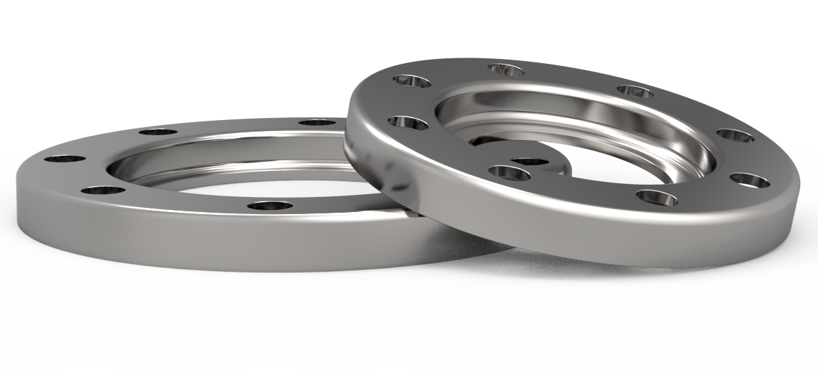
The lap joint flange facilitates alignment during installation thanks to its loose backing ring, making it ideal for installations requiring flexibility and precision.
Standards:
Sizes: 1/2″ ~ 48″
Class: 150 | 300 | 400 | 600 | 900 | 1500 | 2500
| PN6 | PN10 | PN16 | PN25 | PN40 | PN64
Materials: Carbon steel, alloy steel, Duplex steel, Monel K500, Inconel, Inconel 600, etc.
To view all technical specifications, download the PDF for this product.
| BRIDES TOURNANTES ACIER ISO PN10 – (LOOSE PLATE FLANGES, ISO PN10) | |||||||||||
| DN | Alésage (mm) | Ø ext. | Epaisseur | Perçage | Chanfrein | Kg/pc | |||||
| B2-11002 | B3-11003 | D (mm) | C1 (mm) | n x L | Ø K (mm) | e (mm) | TYPE 02A | TYPE 04 A | |||
| 10 | 21 | 31 | 90 | 14 | 4 x 14 | 60 | 3 | 0.5 | 0.5 | ||
| 15 | 25 | 35 | 95 | 14 | 4 x 14 | 65 | 3 | 0.5 | 0.5 | ||
| 20 | 31 | 42 | 105 | 16 | 4 x 14 | 75 | 4 | 1.0 | 1.0 | ||
| 25 | 38 | 49 | 115 | 16 | 4 x 14 | 85 | 4 | 1.0 | 1.0 | ||
| 32 | 47 | 59 | 140 | 18 | 4 x 18 | 100 | 5 | 2.0 | 1.5 | ||
| 40 | 53 | 67 | 150 | 18 | 4 x 18 | 110 | 5 | 2.0 | 2.0 | ||
| 50 | 65 | 77 | 165 | 19 | 4 x 18 | 125 | 5 | 2.5 | 2.5 | ||
| 65 | 81 | 96 | 185 | 20 | 4 x 18 | 145 | 6 | 3.0 | 3.0 | ||
| 80 | 94 | 108 | 200 | 20 | 8 x 18 | 160 | 6 | 3.5 | 3.0 | ||
| 100 | 120 | 134 | 220 | 22 | 8 x 18 | 180 | 6 | 4.5 | 4.0 | ||
| 125 | 145 | 162 | 250 | 22 | 8 x 18 | 210 | 6 | 5.5 | 4.5 | ||
| 150 | 174 | 188 | 285 | 24 | 8 x 22 | 240 | 6 | 7.0 | 6.0 | ||
| 200 | 226 | 240 | 340 | 24 | 8 x 22 | 295 | 6 | 9.0 | 8.0 | ||
| 250 | 281 | 294 | 395 | 26 | 12 x 22 | 350 | 8 | 11.5 | 10.0 | ||
| 300 | 333 | 348 | 445 | 26 | 12 x 22 | 400 | 8 | 13.0 | 11.5 | ||
| 350 | 365 | 400 | 505 | 28 | 16 x 22 | 460 | 8 | 19.5 | 15.0 | ||
| 400 | 416 | 450 | 565 | 32 | 16 x 26 | 515 | 8 | 26.5 | 21.0 | ||
| 450 | 467 | 498 | 615 | 36 | 20 x 26 | 565 | 8 | 32.5 | 26.0 | ||
| 500 | 519 | 550 | 670 | 38 | 20 x 26 | 620 | 8 | 39.0 | 31.0 | ||
| 600 | 622 | 650 | 780 | 42 | 20 x 30 | 725 | 8 | 52.5 | 43.5 | ||
| BRIDES TOURNANTES POINT BLEU ISO PN10 – (LAP JOINT FLANGES, ISO PN10) | |||||||||||
| DN | Dimensions | Percage | Kg / pc | Gain de poids (1) | |||||||
| a (mm) | D (mm) | E (mm) | F (mm) | G (mm) | r1 (mm) | r3 (mm) | n x L | Ø K | |||
| 15 | 3 | 95 | 11.5 | 24 | 38 | 3 | 3 | 4 x 13.5 | 65 | 0.20 | 70 % |
| 20 | 3 | 105 | 14 | 30 | 48 | 3 | 3 | 4 x 13.5 | 75 | 0.25 | 70 % |
| 25 | 3 | 115 | 16 | 38 | 53 | 3 | 3 | 4 x 13.5 | 85 | 0.30 | 62 % |
| 32 | 3 | 140 | 16.5 | 46 | 68 | 3 | 3.5 | 4 x 17.5 | 100 | 0.45 | 62 % |
| 40 | 4 | 150 | 18 | 54 | 77 | 3 | 3.5 | 4 x 17.5 | 110 | 0.62 | 70 % |
| 50 | 4 | 165 | 20 | 65 | 91 | 3 | 4 | 4 x 17.5 | 125 | 0.90 | 65 % |
| 65 | 5 | 185 | 22 | 81 | 108 | 4.5 | 5 | 4 x 17.5 | 145 | 1.20 | 65 % |
| 80 | 5 | 200 | 23 | 94 | 123 | 4.5 | 5 | 8 x 17.5 | 160 | 1.30 | 65 % |
| 100 | 6 | 220 | 24 | 119 | 141 | 5 | 5 | 8 x 17.5 | 180 | 1.75 | 60 % |
| 125 | 6 | 250 | 25.5 | 145 | 168 | 4.5 | 5 | 8 x 17.5 | 210 | 2.20 | 50 % |
| 150 | 6 | 285 | 27 | 173 | 192 | 4.5 | 5 | 8 x 21.5 | 240 | 2.70 | 50 % |
| 200 | 8 | 340 | 31 | 225 | 245 | 5 | 5 | 8 x 21.5 | 295 | 4.60 | 50 % |
ZI des Vallons, Rue du Bistanclaque – 38110 CESSIEU (France) + Tel : +33 (0)4 74 33 83 09 – Mail : go-steel@go-steel.fr
Une marque du groupe GOTREX